
Your Robot Is Repeatable
We Make It Accurate
Robot and machine calibration, measured with a laser tracker, corrected inside the controller you already run, verified before we leave. Same robot, same cell, real accuracy.
What You Get
One visit, and every program after it runs true.
A laser tracker, a true model of your machine with its elasticity in it, and the correction loaded into your controller or, where it cannot take one, into your programs. Checked on held-out poses before we go.
0.10 mm mean, 0.17 mm worst pose
Absolute position error over the volume we measure, on a machine that is mechanically sound; a typical cell starts around half a millimeter. If yours cannot reach the line, we say so before the work, not after.
A machine, a report, a diagnosis
The corrected machine with its tool and turntable references redone, a report you can hold us to, and a reading of what is left: done, or what to fix first.
Your Robot Hits the Same Wrong Spot Every Time
Industrial robots are sold as precise. They are repeatable, which is not the same thing. Send one to the same spot a thousand times and it will come back within a few hundredths of a millimeter. Where that spot actually is can be off by a few tenths of a millimeter, sometimes more than a full millimeter, and the error changes with reach, orientation and payload.
A tight cluster, in the wrong place .
The same cluster, on target.
Scrapped blanks. Failed first-article inspections. Re-teaching by hand. Tolerances quietly opened up to whatever the machine can hold.
A newer robot. It arrives with the same gap, only smaller. Accuracy is not shipped from a factory; it is measured into the machine on your floor.
For Anyone Whose Part Has to Match the CAD
Robotic milling and job shops
Metal, stone, composite, foam, molds. Every tenth of a millimeter of position error can become a scrapped blank or an out-of-tolerance surface. You get absolute accuracy from the cell you already have, with nothing rebuilt.
Robotic additive manufacturing
In wire-arc additive (WAAM) and large-format printing, small pose errors compound bead over bead and layer over layer until the part walks away from the CAD. Calibrating the machine as built takes the pose-dependent part of that error out before the first bead goes down.
Art and architectural fabrication
Complex geometry, no second chance on the material. One-off pieces that have to be right the first time, and the work this calibration was built for.
Integrators, OEMs and distributors
Your customers ask for accuracy, not just repeatability. Hand over cells that are accurate on day one, without buying a tracker or building a metrology team.
Measured Once Every Program After It Runs True
We measure the machine as it really is, build the kinematic model that matches it, and put the correction where your machine can use it: in the controller if it can take a model, in the programs if it cannot. Either way it comes from one measurement, and every program from then on runs accurate, the ones you write tomorrow and the ones you wrote before we arrived. Nothing bolted on. It holds until the machine itself changes; after a crash or a rebuild, we come back.
Measure
A laser tracker follows the tool across the working volume and records where the machine actually went, pose after pose.
Model
From those measurements we build the machine's true model: its geometry and its elasticity, solved together. The correction covers the working volume we measured: the poses themselves and everything between.
Load
Into the controller where it can hold a model, KUKA with the Absolute Accuracy option or Siemens Sinumerik: no hardware swap, no external box, no change to how you program, and every program picks the correction up by itself. Where it cannot, an older cabinet without the option, say, into the programs: the same model corrects each one on its way to the machine, from any CAM.
Verify
We check the correction on poses we kept back from the calibration, and put the result on one page. That page is what you plan production around.
Not a Patch , Not a Guess, Not a New Machine
One model, two ways to carry it
If your controller takes a model, the correction lives there and your CAM chain never has to know. If it does not, we correct the programs instead, from the same measurement. You never choose between accuracy and the controller you have.
The tracker comes with us
We fit the model to what a metrology-grade laser tracker measured on your machine. You do not buy the tracker, learn it or store it. It travels with us and goes home with us.
Elasticity, not just geometry
Advanced mathematical models that do not stop at link lengths and joint offsets: they carry the machine's elasticity, how the structure deflects under its own weight and the tool it carries, solved together with the geometry. That is what keeps a heavy tool at full reach inside the correction rather than outside it.
One method, many machines
Articulated KUKA robots and parallel-kinematic tripods such as the Exechon. One method for both, not a pile of machine-specific hacks.
Not the factory's calibration
The robot maker calibrates a bare robot on the day it ships. We calibrate the cell you actually run: your tool, your mount, your floor, your temperature, and again after anything changes.
Checked, not claimed
Every number we give is verified on poses kept out of the fit, and every step of this was worked out on real jobs, with deadlines and no spare material. Where the data does not support a claim, you see the range instead.
What We Hold Your Machine To
This is not a typical result. It is the line we calibrate to, checked on poses the fit never saw. If the measurement says your machine cannot reach it, you hear that before the calibration, not after.
| Measure | Out of the factory, typical | After calibration |
|---|---|---|
| Mean position error | about 0.5 | 0.10 |
| Worst pose | about 0.8 | 0.17 |
Absolute position error, read by a laser tracker good to a few hundredths, against a model that carries geometry and elasticity together. A machine that clears this line on verification poses is a machine you can plan around.
A Report You Can Hold Us To
Every calibration ends with one: what the error was, what it is now, and what it is on poses we never used to build the model . That last figure is the honest one. Any model can be made to fit the data it was given. Only poses it never saw show whether it learned the machine or memorized the measurements. Below, a sample report against the line above: a mean of 0.058 mm inside the 0.10 we hold to, a worst pose of 0.128 inside the 0.17, and the poses kept back agreeing with the rest.
Measured with an instrument worth ±0.030 mm.
from 0.532 mm, measured after alignment
acceptance is decided here
worst 0.111 mm · kept out of the fit but sitting between the poses in it, so this says the fit did not simply memorise them
And What Is Left Tells You Why
Most calibrations hand you a number and stop. We read what is left. The leftover error has a shape, and the shape has a cause: noise means you are done; a pull along one axis, a growth across the volume, or a clump in one corner means something in the machine or the setup, and tells you where to look. So the report does not only say how good the machine is. It says whether you are done, and if not, what to fix first.
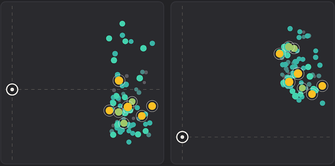
Scattered, pulling in no direction, the size of the instrument: measurement noise. The calibration is finished.
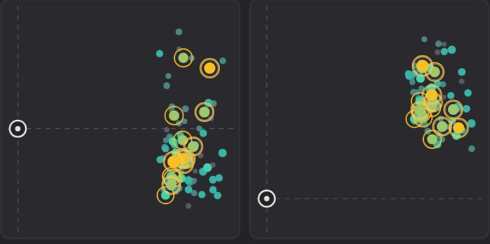
Z spreads 3.7 times wider than the instrument. The model cannot explain it, so the fault is in the machine, and you know which axis to look at before the next job.
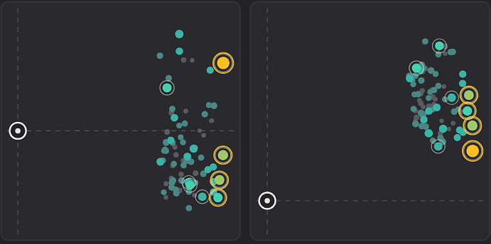
The error grows with reach: the further out the arm, the lower it sits. No kinematics does that. Something under the robot gives, the base or the mount. Bolt it down and measure again.
Tell Us the Machine the Part and the Tolerance You Are Fighting
The machine you run, a photo or drawing of the part, and the tolerance you have to hold: that is all we need to say whether it fits, which route your controller takes, and what it takes to do it. Then we come, measure, and show you before and after on your own machine. Already own a tracker? Send us the measurements and we take it from there.
Built in production, not in a lab. Minotor Labs is the calibration arm of a robotic-fabrication studio in Connecticut, a shop that has spent years machining demanding sculptural and architectural work with robots, where close enough is not close enough. We built the calibration for our own parts first, and measured it until we trusted it on other people's.
Contact Us
Tell us the machine, the part, and the tolerance you are fighting, or fill out the form below. We will tell you whether it fits and what it takes.